(!)Due to Microsoft's end of support for Internet Explorer 11 on 15/06/2022, this site does not support the recommended environment.
Instead, please kindly use other browsers like Google Chrome, Microsoft Edge or Mozilla Firefox.
50,000 Stock items for Same Day Ship Out.
All Categories
Categories
- Automation Components
A wide variety of standard and configurable components for factory automation engineers in industries such as automotive, semiconductor, packaging, medical and many more.
- Linear Motion
- Rotary Motion
- Connecting Parts
- Rotary Power Transmission
- Motors
- Conveyors & Material Handling
- Locating, Positioning, Jigs & Fixtures
- Inspection
- Sensors, Switches
- Pneumatics, Hydraulics
- Vacuum Components
- Hydraulic Equipment
- Discharging / Painting Devices
- Pipe, Tubes, Hoses & Fittings
- Modules, Units
- Heaters, Temperature Control
- Framing & Support
- Casters, Leveling Mounts, Posts
- Doors, Cabinet Hardware
- Springs, Shock Absorbers
- Adjusting, Fastening, Magnets
- Antivibration, Soundproofing Materials, Safety Products
- Fasteners
A good selection of accessories such as screws, bolts, washers and nuts that you may need for your daily engineering usage.
- Materials
Browse industrial materials ranging from heat insulating plates, sponges, to metal and plastic materials in different sizes to meet your various applications.
- Wiring Components
A wide variety of wiring parts for connecting and protecting control and PC parts including Connectors, Cables, Electric Wires, Crimping Terminals and more.
- LAN Cables / Industrial Network Cables
- Cables by Application
- Cables with Connectors
- RS232 / Personal Computers / AV Cables
- Wires/Cables
- Connectors (General Purpose)
- Crimp Terminals
- Zip Ties
- Cable Glands
- Cable Bushings/Clips/Stickers
- Screws/Spacers
- Cable Accessories
- Tubes
- Protection Tubes
- Ducts/Wiremolds
- General Purpose Tools
- Dedicated Tools
- Soldering Supplies
- Electrical & Controls
A wide variety of controls and PC parts for electrical engineers including Controls, Powers, PC parts and more.
- Cutting Tools
A wide variety of cutting tools for many uses and work materials including End Mills, Drills, Cutters, Reamers, Turning Tools and more.
- Carbide End Mills
- HSS End Mills
- Milling Cutter Inserts/Holders
- Customized Straight Blade End Mills
- Dedicated Cutters
- Turning Tools
- Drill Bits
- Screw-Hole-Related Tools
- Reamers
- Chamfering / Centering Tools
- Fixtures Related to Cutting Tools
- Step Drills
- Hole Saws
- Clean Key Cutters
- Core Drills (Tip Tools)
- Magnetic Drilling Machine Cutters
- Drill Bits for Electric Drilling Machines
- Woodworking Drill Cutters
- Drills for Concrete
- Processing Tools
A wide variety of tools and supplies used in processing including Machine Tools, Measurement Tools, Grinding and Polishing Supplies and more.
- Material Handling & Storage
A wide variety of goods used in shipment, material handling and warehouse including Tape supplies, Stretch film, Truck, Shelf, Crane and more.
- Tape Supplies
- Cushioning Materials
- Stretch Films
- Cardboard
- Plastic Bags
- PP Bands
- Magic Tapes / Tying Belts
- Rubber Bands
- Strings/Ropes
- Cable Ties
- Tags
- Labelers
- Unpacking Cutters
- Packing Support Equipment
- Cloth Sheets for Packing
- Conveyance/Dolly Carts
- Tool Wagons
- Tool Cabinets / Container Racks
- Lifters / Hand Pallets
- Container Pallets
- Storage Supplies
- Shelves/Racks
- Work Benches
- Suspended Clamps/Suspended Belts
- Jack Winches
- Chain Block Cranes
- Bottles/Containers
- Bicycle Storage Area
- Safety & General Supplies
A large variety of goods for every kind of factories and offices including Protection items, Cleaning supplies, sanitations, office supplies and more.
- Lab & Clean Room Supplies
A large variety of items used in R&D and Clean Room including research Equipment, Laboratory Essentials, Analysis Supplies, Clean Environment-Related Equipment and more.
- Press Die Components
Choose from thousands of standard stamping die components including Punch & Die, Gas Springs, Guide Components, Coil Springs and many more.
- Plastic Mold Components
Browse our wide variety of mold components including Ejector Pins, Sleeves, Leader Components, Sprue Bushings and many more.
- Ejector Pins
- Sleeves, Center Pins
- Core Pins
- Sprue bushings, Gates, and other components
- Date Mark Inserts, Recycle Mark Inserts, Pins with Gas Vent
- Undercut, Plates
- Leader Components, Components for Ejector Space
- Mold Opening Controllers
- Cooling or Heating Components
- Accessories, Others
- Components of Large Mold, Die Casting
- Injection Molding Components
Browse our injection molding components including Heating Items, Couplers, Hoses and more.
- Injection Molding Machine Products
- Accessories of Equipment
- Auxiliary Equipment
- Air Nippers
- Air Cylinders
- Air Chuck for Runner
- Chuck Board Components
- Frames
- Suction Components
- Parallel Air Chuck
- Special Air Chuck
- Chemical for Injection Molding
- Mold Maintenance
- Heating Items
- Heat Insulation Sheets
- Couplers, Plugs, One-touch Joints
- Tubes, Hoses, Peripheral Components
Search by Application
Brands
- Notice of End of Sales for Economy Series Pneumatic Equipment Category. More information.
Low Speed Rotary Table, Rack And Pinion Type, MSQX Series (Part Numbers)
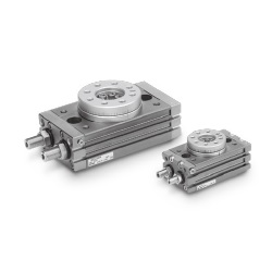
[Features]
· Possible to transfer workpieces at low speeds.
· Achieves stable motion at 5s/90°.
& nbspSmooth motion without stick-slip phenomenon.
· Rotation time adjustment range: 1 to 5 (s/90°).
(i)Caution
- Refer to the catalog for details on product specifications.
- Product images may be representative. Refer to the manufacturer's catalog for details.
Part Number
Configured Part Number is shown.
MSQX Series Low-Speed Rotary Table, Rack & Pinion Type Specifications
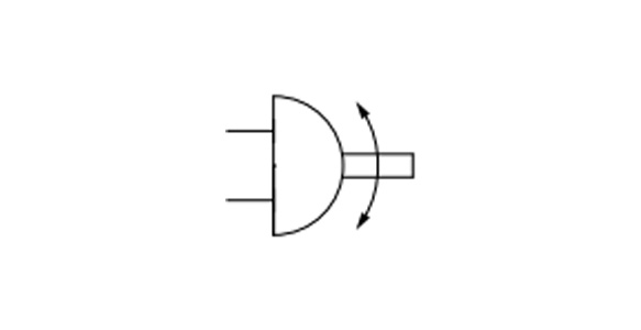
MSQX Series JIS symbol
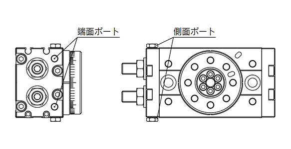
MSQX Series end port / side port diagrams
| Size | 10 | 20 | 30 | 50 | |
|---|---|---|---|---|---|
| Fluid | Air (non-lube) | ||||
| Max. operating pressure | 1 MPa | ||||
| Min. operating pressure | 0.1 MPa | ||||
| Ambient and fluid temperature | 0 to 60°C (no freezing) | ||||
| Cushion | None | ||||
| Angle adjustment range | 0 to 190 ° | ||||
| Maximum rotation angle | 190 ° | ||||
| Port size | End port | M5 × 0.8 | Rc1/8, G1/8, NPT1/8, NPTF1/8 | ||
| Side port | M5 × 0.8 | ||||
| Output (N·m)* | 0.89 | 1.8 | 2.7 | 4.6 | |
*Output under operating pressure of 0.5 MPa. See the manufacturer's catalog for details.
Allowable Kinetic Energy and Rotation Time Adjustment Range
Allowable kinetic energy
- Size 10: 0.007 J
- Size 20: 0.025 J
- Size 30: 0.048 J
- Size 50: 0.081 J
Stable operational rotation time adjustment range
- 1 to 5s/90 °
*If operated where the kinetic energy exceeds the allowable value, this may cause damage to the internal parts and result in product failure. Please pay special attention to the kinetic energy levels when designing, adjusting and during operation to avoid exceeding the allowable limit.
Weight
Basic type
- Size 10: 500 g
- Size 20: 940 g
- Size 30: 1,230 g
- Size 50: 1,990 g
*Values above do not include auto switch weight.
External dimensional drawing
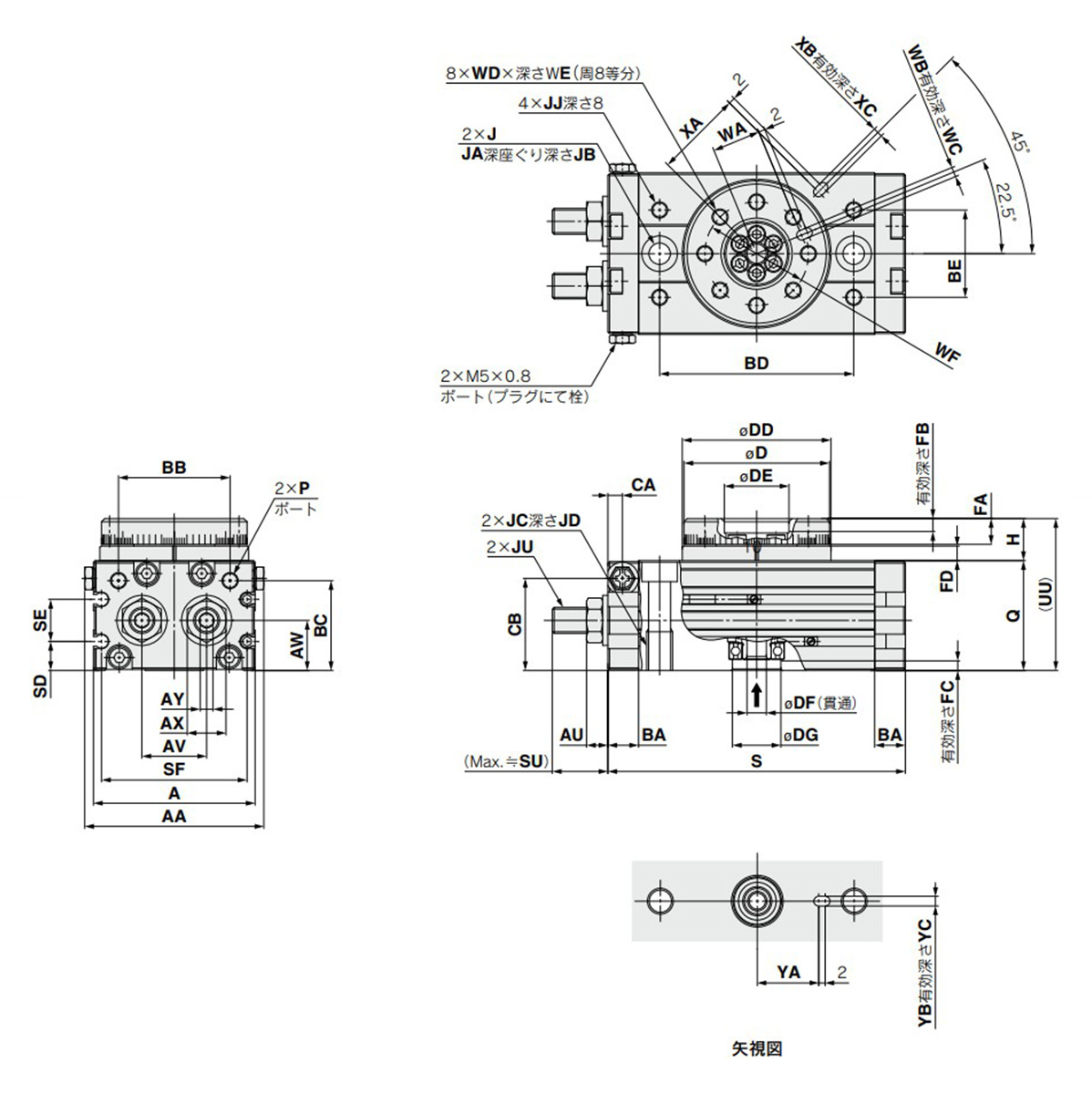
Basic / MSQXB□A dimensional drawing
(Unit: mm)
| Size | AA | A | AU | AV | AW | AX | AY | BA | BB | BC | BD | BE | CA | CB |
|---|---|---|---|---|---|---|---|---|---|---|---|---|---|---|
| 10 | 55.4 | 50 | 6.6 | 20 | 15.5 | 12 | 4 | 9.5 | 34.5 | 27.8 | 60 | 27 | 4.5 | 28.5 |
| 20 | 70.8 | 65 | 7.6 | 27.5 | 16 | 14 | 5 | 12 | 46 | 30 | 76 | 34 | 6 | 30.5 |
| 30 | 75.4 | 70 | 7.6 | 29 | 18.5 | 14 | 5 | 12 | 50 | 32 | 84 | 37 | 6.5 | 33.5 |
| 50 | 85.4 | 80 | 10 | 38 | 22 | 19 | 6 | 15.5 | 63 | 37.5 | 100 | 50 | 10 | 37.5 |
| Size | D | DD | DE | DF | DG | FA | FB | FC | FD | H | J | JA | JB |
|---|---|---|---|---|---|---|---|---|---|---|---|---|---|
| 10 | 45h9 | 46h9 | 20H9 | 6 | 15H9 | 8 | 4 | 3 | 4.5 | 13 | 6.8 | 11 | 6.5 |
| 20 | 60h9 | 61h9 | 28H9 | 9 | 17H9 | 10 | 6 | 2.5 | 6.5 | 17 | 8.6 | 14 | 8.5 |
| 30 | 65h9 | 67h9 | 32H9 | 12 | 22H9 | 10 | 4.5 | 3 | 6.5 | 17 | 8.6 | 14 | 8.5 |
| 50 | 75h9 | 77h9 | 35H9 | 13 | 26H9 | 12 | 5 | 3 | 7.5 | 20 | 10.5 | 18 | 10.5 |
(Unit: mm)
| Size | JC | JD | JJ | JU | P | Q | S | SD | SE | SF |
|---|---|---|---|---|---|---|---|---|---|---|
| 10 | M8 × 1.25 | 12 | M5 × 0.8 | M8 × 1 | M5 × 0.8 | 34 | 92 | 9 | 13 | 45 |
| 20 | M10 × 1.5 | 15 | M6 × 1 | M10 × 1 | M5 × 0.8 | 37 | 117 | 10 | 12 | 60 |
| 30 | M10 × 1.5 | 15 | M6 × 1 | M10 × 1 | Rc1/8** | 40 | 127 | 11.5 | 14 | 65 |
| 50 | M12 × 1.75 | 18 | M8 × 1.25 | M14 × 1.5 | Rc1/8** | 46 | 152 | 14.5 | 15 | 75 |
| Size | SU | UU | WA | WB | WC | WD | WE | WF | XA | XB | XC | YA | YB | YC |
|---|---|---|---|---|---|---|---|---|---|---|---|---|---|---|
| 10 | 17.7 | 47 | 15 | 3H9 | 3.5 | M5 × 0.8 | 8 | 32 | 27 | 3H9 | 3.5 | 19 | 3H9 | 3.5 |
| 20 | 25 | 54 | 20.5 | 4H9 | 4.5 | M6 × 1 | 10 | 43 | 36 | 4H9 | 4.5 | 24 | 4H9 | 4.5 |
| 30 | 25 | 57 | 23 | 4H9 | 4.5 | M6 × 1 | 10 | 48 | 39 | 4H9 | 4.5 | 28 | 4H9 | 4.5 |
| 50 | 31.4 | 66 | 26.5 | 5H9 | 5.5 | M8 × 1.25 | 12 | 55 | 45 | 5H9 | 5.5 | 33 | 5H9 | 5.5 |
**In addition to Rc1/8, G1/8, NPT1/8, NPTF1/8 are also available.
Rotation Direction and Rotation Angle
- The rotary table turns in the clockwise direction when the A port is pressurized, and in the counterclockwise direction when the B port is pressurized.
- By adjusting the adjustment bolt, the rotation end can be set within the range shown in the drawing for the desired rotation angle.
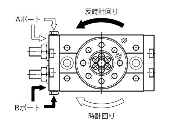
Diagram: rotation direction
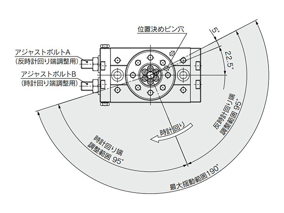
Diagram: rotation angle
- *The drawing shows the rotation range of the positioning pin hole.
- *The pin hole position in the drawing shows the counterclockwise rotation end when the adjustment bolts A and B are tightened equally and the rotation is adjusted 180°.
With external shock absorber / adjustment angle per rotation of angle adjusting screw
- Size 10: 10.2 °
- Size 20: 7.2 °
- Size 30: 6.5 °
- Size 50: 8.2 °
Rotation Angle Range Example
Various rotation ranges are possible as shown in the drawings below using adjustment bolts A and B.
(The drawings also show the rotation ranges of the positioning pin.)
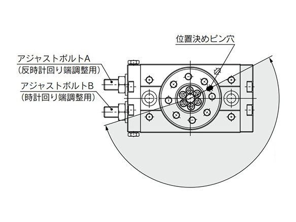
190° (maximum) rotation
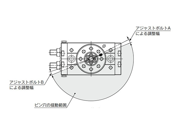
180° rotation
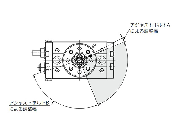
90° rotation
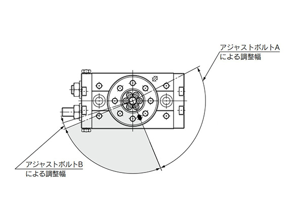
90° rotation
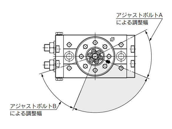
90° rotation
Precautions
Speed Adjustment
- *Changes in speed occur in applications in which there are changes to the load during operation, such as the load being lifted (lowered) against gravity.
- *The purpose of this product is stable rotation at low speed. It does not provide any function to cushion the impact at the operation start or end.
- *Speed may vary at the rotation end depending on operating conditions. (This can be avoided by setting the external stopper.)
*See the manufacturer's catalog for product information other than the above.
| Part Number |
|---|
| Part Number | Minimum order quantity | Volume Discount | Days to Ship | Oscillation Angle A | Torque (N・m) | Operation Method | Tube Nominal Dia. | Allowable Kinetic Energy (J) | Allowable Kinetic Energy (J) | Size | Connection port location | Switch | Lead wire (m) | Number of switches | Port types | Connector type | Specifications |
|---|
Loading...
Basic Information
| Type | Rotary Table 2-point Stop | Main Body Shape | Block Shape | Environment, Applications | Slow Speed |
|---|---|---|---|---|---|
| Rigidity, Accuracy | Standard | Valves | N/A | Operating Pressure Range(MPa) | 0.1::1 |
Specification/Dimensions
-
Oscillation Angle A
- 90°
- 180°
- 190°
- 90°
-
Torque(N・m)
- 1 to Less Than 3
- 3 ~ Less than 6
- 6 to Less Than 10
-
Operation Method
- Single Rack
- Double Rack
-
Tube Nominal Dia.
-
Allowable Kinetic Energy(J)
- 0.005 to Less Than 0.01
- 0.01 to Less Than 0.1
-
Allowable Kinetic Energy(J)
-
Size
-
Connection port location
- Standard type
- Symmetrical type
-
Switch
-
Lead wire(m)
- 0.5
- 1
- 3
- 5
- None
-
Number of switches
- 1 pc.
- 2 pcs.
- 3 pcs.
- 4 pcs.
- 6 pcs.
- 11 pcs.
- None
-
Port types
-
Connector type
- M8 3-pin
- M8 4-pin
- M12 4-pin
- None
-
Specifications
- Made to order specifications
- Standard type
-
type
- MSQXB10□
- MSQXB20□
- MSQXB30□
- MSQXB50□
-
CAD
- 2D
- 3D
Days to Ship
-
- All
- 32 Day(s) or Less
Specify Alterations
- The specifications and dimensions of some parts may not be fully covered. For exact details, refer to manufacturer catalogs .


How can we improve?
How can we improve?