(!)Due to Microsoft's end of support for Internet Explorer 11 on 15/06/2022, this site does not support the recommended environment.
Instead, please kindly use other browsers like Google Chrome, Microsoft Edge or Mozilla Firefox.
50,000 Stock items for Same Day Ship Out.
All Categories
Categories
- Automation Components
A wide variety of standard and configurable components for factory automation engineers in industries such as automotive, semiconductor, packaging, medical and many more.
- Linear Motion
- Rotary Motion
- Connecting Parts
- Rotary Power Transmission
- Motors
- Conveyors & Material Handling
- Locating, Positioning, Jigs & Fixtures
- Inspection
- Sensors, Switches
- Pneumatics, Hydraulics
- Vacuum Components
- Hydraulic Equipment
- Discharging / Painting Devices
- Pipe, Tubes, Hoses & Fittings
- Modules, Units
- Heaters, Temperature Control
- Framing & Support
- Casters, Leveling Mounts, Posts
- Doors, Cabinet Hardware
- Springs, Shock Absorbers
- Adjusting, Fastening, Magnets
- Antivibration, Soundproofing Materials, Safety Products
- Fasteners
A good selection of accessories such as screws, bolts, washers and nuts that you may need for your daily engineering usage.
- Materials
Browse industrial materials ranging from heat insulating plates, sponges, to metal and plastic materials in different sizes to meet your various applications.
- Wiring Components
A wide variety of wiring parts for connecting and protecting control and PC parts including Connectors, Cables, Electric Wires, Crimping Terminals and more.
- LAN Cables / Industrial Network Cables
- Cables by Application
- Cables with Connectors
- RS232 / Personal Computers / AV Cables
- Wires/Cables
- Connectors (General Purpose)
- Crimp Terminals
- Zip Ties
- Cable Glands
- Cable Bushings/Clips/Stickers
- Screws/Spacers
- Cable Accessories
- Tubes
- Protection Tubes
- Ducts/Wiremolds
- General Purpose Tools
- Dedicated Tools
- Soldering Supplies
- Electrical & Controls
A wide variety of controls and PC parts for electrical engineers including Controls, Powers, PC parts and more.
- Cutting Tools
A wide variety of cutting tools for many uses and work materials including End Mills, Drills, Cutters, Reamers, Turning Tools and more.
- Carbide End Mills
- HSS End Mills
- Milling Cutter Inserts/Holders
- Customized Straight Blade End Mills
- Dedicated Cutters
- Turning Tools
- Drill Bits
- Screw-Hole-Related Tools
- Reamers
- Chamfering / Centering Tools
- Fixtures Related to Cutting Tools
- Step Drills
- Hole Saws
- Clean Key Cutters
- Core Drills (Tip Tools)
- Magnetic Drilling Machine Cutters
- Drill Bits for Electric Drilling Machines
- Woodworking Drill Cutters
- Drills for Concrete
- Processing Tools
A wide variety of tools and supplies used in processing including Machine Tools, Measurement Tools, Grinding and Polishing Supplies and more.
- Material Handling & Storage
A wide variety of goods used in shipment, material handling and warehouse including Tape supplies, Stretch film, Truck, Shelf, Crane and more.
- Tape Supplies
- Cushioning Materials
- Stretch Films
- Cardboard
- Plastic Bags
- PP Bands
- Magic Tapes / Tying Belts
- Rubber Bands
- Strings/Ropes
- Cable Ties
- Tags
- Labelers
- Unpacking Cutters
- Packing Support Equipment
- Cloth Sheets for Packing
- Conveyance/Dolly Carts
- Tool Wagons
- Tool Cabinets / Container Racks
- Lifters / Hand Pallets
- Container Pallets
- Storage Supplies
- Shelves/Racks
- Work Benches
- Suspended Clamps/Suspended Belts
- Jack Winches
- Chain Block Cranes
- Bottles/Containers
- Bicycle Storage Area
- Safety & General Supplies
A large variety of goods for every kind of factories and offices including Protection items, Cleaning supplies, sanitations, office supplies and more.
- Lab & Clean Room Supplies
A large variety of items used in R&D and Clean Room including research Equipment, Laboratory Essentials, Analysis Supplies, Clean Environment-Related Equipment and more.
- Press Die Components
Choose from thousands of standard stamping die components including Punch & Die, Gas Springs, Guide Components, Coil Springs and many more.
- Plastic Mold Components
Browse our wide variety of mold components including Ejector Pins, Sleeves, Leader Components, Sprue Bushings and many more.
- Ejector Pins
- Sleeves, Center Pins
- Core Pins
- Sprue bushings, Gates, and other components
- Date Mark Inserts, Recycle Mark Inserts, Pins with Gas Vent
- Undercut, Plates
- Leader Components, Components for Ejector Space
- Mold Opening Controllers
- Cooling or Heating Components
- Accessories, Others
- Components of Large Mold, Die Casting
- Injection Molding Components
Browse our injection molding components including Heating Items, Couplers, Hoses and more.
- Injection Molding Machine Products
- Accessories of Equipment
- Auxiliary Equipment
- Air Nippers
- Air Cylinders
- Air Chuck for Runner
- Chuck Board Components
- Frames
- Suction Components
- Parallel Air Chuck
- Special Air Chuck
- Chemical for Injection Molding
- Mold Maintenance
- Heating Items
- Heat Insulation Sheets
- Couplers, Plugs, One-touch Joints
- Tubes, Hoses, Peripheral Components
Search by Application
Brands
- Notice of End of Sales for Economy Series Pneumatic Equipment Category. More information.
ALB900 Series Booster Lube (ALB900-30-15)
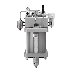
Booster lube enables stable oil feeding with a micromist.
[Features]
· Centralized control of multi-point lubrication.
· Through the use of a booster, a pressure that is higher than that of the main air passage can be supplied.
· This difference is used as the mist generating pressure differential. Thus, the pressure drop in the main air passage is minimized.
· Micromist can be constantly supplied by merely adjusting the mist generating pressure differential.
· Oil can be replenished by merely opening and closing the oil filler plug without stopping the air line.
· The condition of the generation of micromist can be checked from the oil filler port.
· Standard accessories: bypass lubrication adapter / ball valve / ball valve.
· Option: float switch.
(i)Caution
- See catalog for specification details.
- Product images may be representative images. Refer to the catalog for details.
Part Number
Configured Part Number is shown.
ALB900-30-15
ALB900 Series Booster Lube Specifications
| Model | ALB900-10 | ALB900-20 | ALB900-30 |
|---|---|---|---|
| Port (bypass lubrication adapter) | Rc1 | Rc2 | 3-inch flange |
| Port size (body) | IN: Rc1/4 OUT: Rc1/2 | ||
| Applicable fluids | Air | ||
| Proof pressure | 1.5 MPa | ||
| Operating pressure range | 0.4 to 1.0 MPa | ||
| Operating pressure differential range | 0.05 to 0.2 MPa | ||
| Bowl capacity between levels (cm3) | 5,000 | ||
| Recommended lubricant | Type 1 turbine oil (additive-free) ISO VG32 | ||
| Ambient temperature and working fluid temperature | 5 to 50°C | ||
| Bowl material | Glass fiber epoxy resin, polycarbonate | ||
| Weight (kg) | 28 | ||
Float Switch Specifications
- Voltage: 200 V AC, 200 V DC
- Max. contact capacity: 50 VA AC, 50 W DC
- Max. operating current: 0.5 A AC, 0.5 A DC
- Contact point: 1a, 1b
- Level indication: bottom limit indication
Outline dimensional drawing
(Unit: mm)
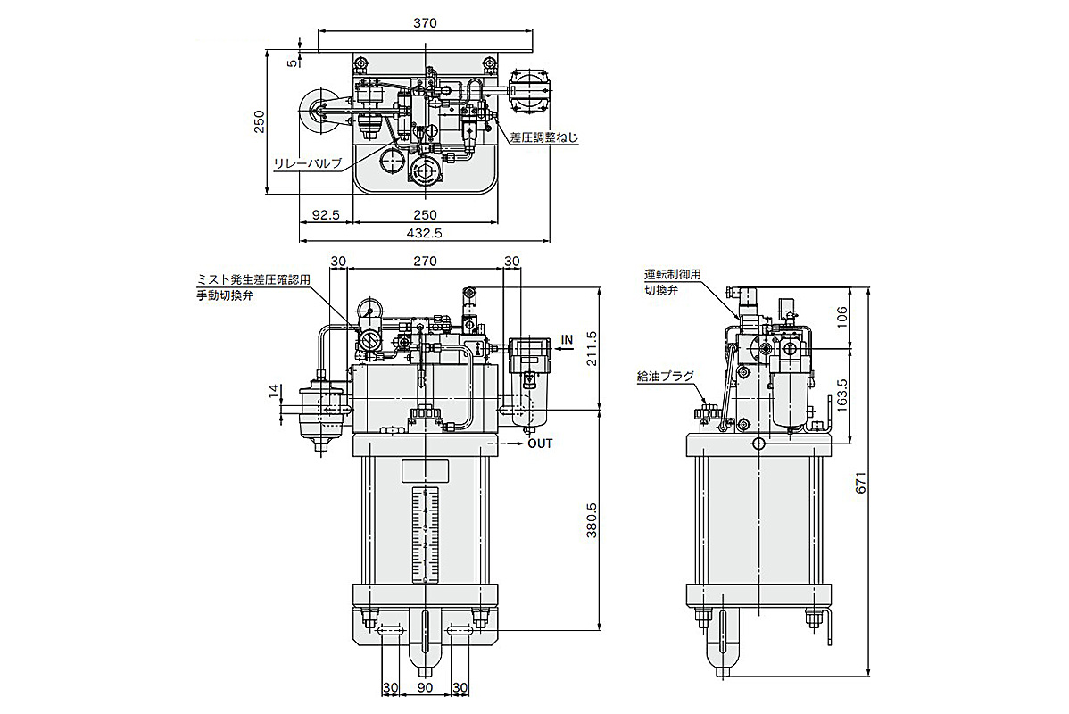
ALB900--1 dimensional drawing
Structural drawing
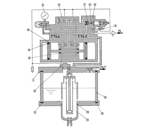
ALB900 Series structure drawing
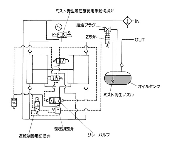
Circuit diagram: ALB900 Series
Component parts
| Number | Part name | Material |
|---|---|---|
| 1 | Top cover | Cast aluminum |
| 2 | Bottom cover | Cast aluminum |
Replacement parts
| Number | Part name | Material | Quantity | |
|---|---|---|---|---|
| 3 | 3-port switching valve (for operation control) | - | 1 | |
| 4 | Relay valve | - | 1 | |
| 5 | Pressure gauge | - | 1 | |
| 6 | Diaphragm assembly | - | 1 | |
| 7 | Valve assembly | - | 1 | |
| 8 | Gasket set | NLP seal | NBR | 1 |
| 9 | PNY seal | NBR | 1 | |
| 10 | Wear ring | Cloth-inserted phenol aldehyde resin | 1 | |
| 11 | “O-ring | NBR | 1 | |
| 12 | Bowl assembly | Glass fiber-inserted epoxy resin | 1 | |
| 13 | Seal | NBR | 2 | |
| 14 | Lubrication plug assembly | Zinc die-cast NBR | 1 | |
| 15 | Bowl assembly | - | 1 | |
| 16 | “O-ring | NBR | 1 | |
| - | Booster assembly (including [3] to [11]) | - | 1 | |
Piping Example
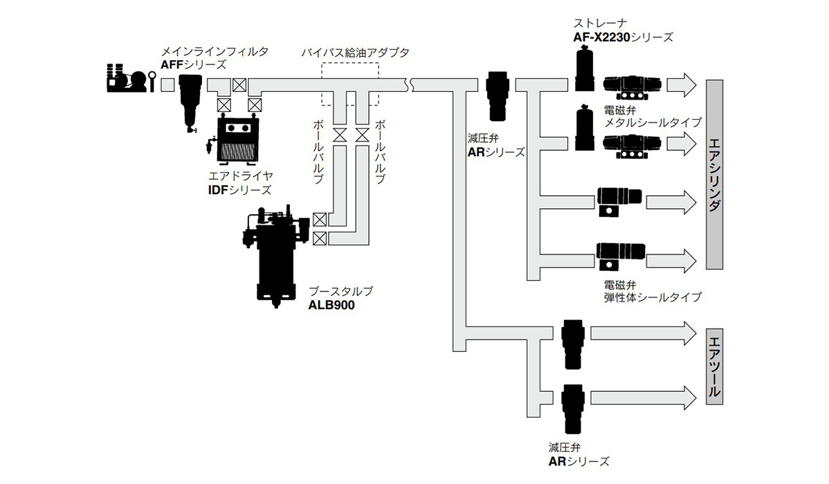
ALB900 Series piping example
Operation Control Method
As shown in the diagram below, reverse the position of the function plate of the switching valve for operation control, and place it in the NO position or in the unmarked position. When the control signal is input, select the state of the operation or the stopping of Booster Lube.
NO position: operate at control signal input
Nil position: stop at control signal input
The 100 V AC, 200 V AC, 220 V AC, 24 V DC, or air pilot type specification can be applied to the control signal.
*The position of the function plate at the time of product shipment is Nil.
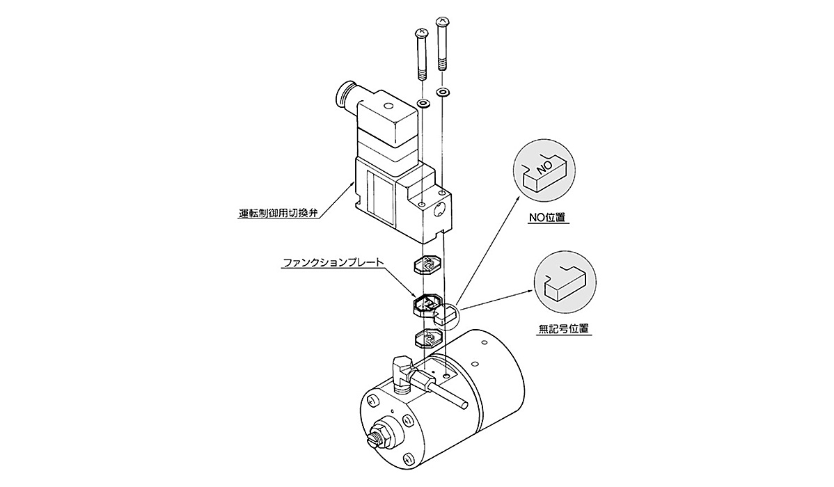
Operation control diagram
Air Consumption
This unit uses a booster to generate a mist generating pressure differential. Therefore, the booster consumes and discharges the air.
Data (A) indicates the relationship between this air consumption rate, the set pressure differential, and the pressure of the main air passage (inlet pressure).
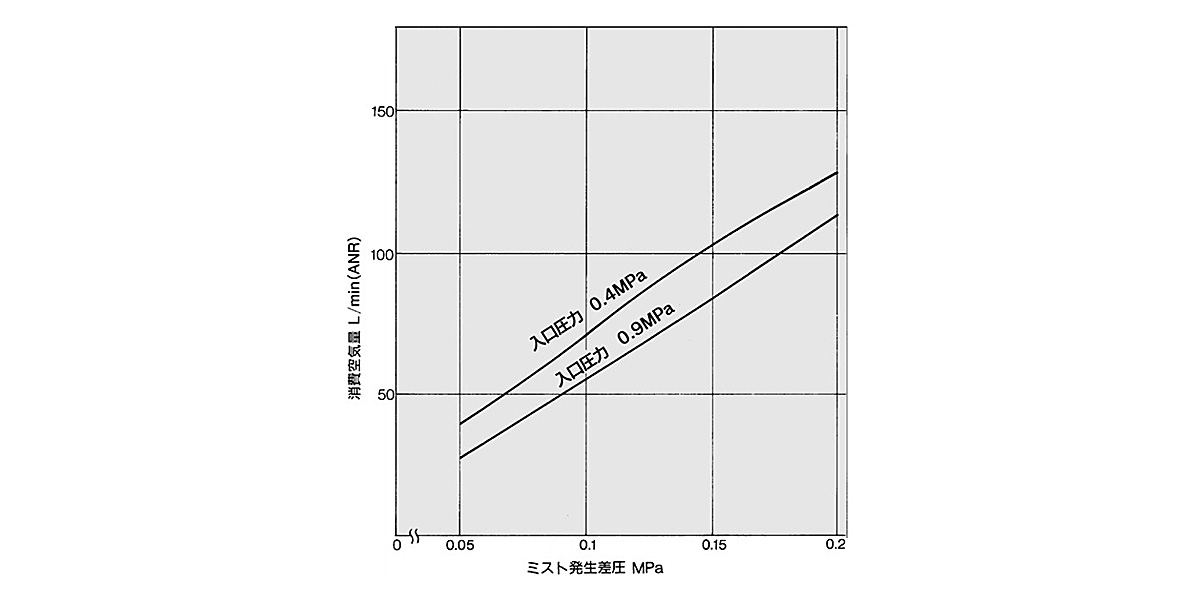
Data (A) air consumption graph
Setting of Mist Generation Pressure Differential
Procedure
- 1. Obtain the air consumption flow rate in the downstream of Booster Lube.
- 2. Obtain the necessary mist generation pressure differential from data (B).
- 3. The mist generating pressure differential setting is performed by adjusting the adjustment screw. The pressure differential (the difference between the boost pressure and the line pressure) is increased by turning the adjustment screw clockwise, and decreased by turning counterclockwise.
To check the pressure differential, switch and operate the manual switching valve to read the difference between the boost pressure (HIGH position) and the line pressure (NORMAL position) as shown below (the pressure gauge that is connected to the manual switching valve).
After completing the setting, set the manual switching valve to the position of the line pressure indication. Do not set the mist generating pressure differential to exceed 0.2 MPa.
How to Read the Graph
Example: How to obtain the mist generating pressure differential if the flow rate obtained in step 1 above is 35 m3/min (ANR) and the line pressure (inlet pressure P1) is 0.7 MPa:
→ Extend horizontally from the point at which the flow rate is 35 m3/min (ANR) to obtain the point that intersects with P1 = 0.7 MPa. Furthermore, extend vertically downward from that point to the point that intersects with the graduation line of the mist generating pressure differential. The value of that intersecting point, which is 0.15 MPa, is the mist generating pressure differential that is sought.
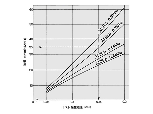
Data (B) flow: mist generation pressure differential graph
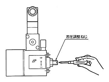
Setting of Mist Generation Pressure Differential
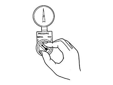
NORMAL position indicates line pressure
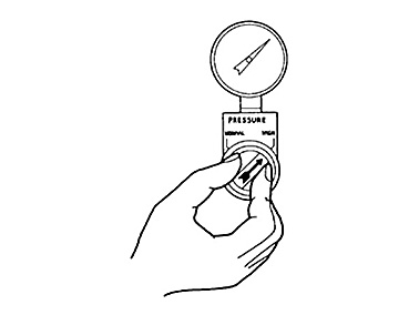
HIGH position indicates boost
Precautions
Caution on Design
*Epoxy resin containing glass fiber and polycarbonate is used in some parts of Booster Lube. These units cannot be used in an environment or in a location that is exposed to synthetic oil, thinner, acetone, alcohol, organic solvents such as ethylene chloride, chemicals such as sulfuric acid or nitric acid, cutting oil, kerosene, gasoline, or a threadlock agent, etc., because they will be damaged.
Piping
*If installing an air tank, install it upstream of the bypass oil feed adapter. If it is installed downstream, the micromist could be arrested by the air tank, which could lead to insufficient feeding of oil.
Mounting/Adjustment
- *When setting the pressure differential, if there is a fluctuation in the operating flow rate, set the pressure differential to the higher flow rate range. If it is set to the lower flow rate range, the mist density could become thinner, leading to poor lubrication.
- *To prevent mist from being generated unnecessarily, if there is no air consumption in the main air passage, operate the switching valve for operation control to stop the operation of the booster.
Maintenance and Inspection
*Before removing the oil filler plug, loosen it two and a half turns to completely release the pressure inside the case. This will prevent the oil filler plug from flying out.
*See the manufacturer's catalog for product information other than the above.
| Part Number |
|---|
| ALB900-30-15 |
| Part Number | Standard Unit Price | Minimum order quantity | Volume Discount | Days to Ship | Float switch | Connection port size | Operation control method | Operation control signal |
|---|---|---|---|---|---|---|---|---|
SGD 7,920.03 | 1 Piece(s) | 32 Day(s) | None | 3-inch flange | Solenoid | 24 V DC |
Loading...
Basic Information
| Oil Storage Capacity(cm3) | 5,000 | IN Side, Connection Type | Rc | IN Side, Plumbing Thread Nominal | 1/4 |
|---|---|---|---|---|---|
| Drain Exhaust | No | Case | Glass Fiber Epoxy Resin, Polycarbonate | OUT Side, Connection Type | Rc |
| OUT Side, Plumbing Thread Nominal | 1/2 | Size of Body | 2-inch standard |
Please check the type/dimensions/specifications of the part ALB900-30-15 in the ALB900 Series Booster Lube series.
Specification/Dimensions
-
type
- ALB900-00-□
- ALB900-10-□
- ALB900-20-□
- ALB900-30-□
-
Float switch
-
Connection port size
- Rc1
- Rc2
- 3-inch flange
- None
-
Operation control method
- Air pilot
- Solenoid
-
Operation control signal
- 24 V DC
- 100 V AC
- 200 V AC
- 220 V AC
- Air pilot
-
CAD
- 2D
- 3D
Days to Ship
-
- All
- 32 Day(s) or Less
Specify Alterations
- The specifications and dimensions of some parts may not be fully covered. For exact details, refer to manufacturer catalogs .
Similar Part Numbers
| Part Number |
|---|
| ALB900-00-00-S2 |
| ALB900-00-11 |
| ALB900-00-11-S1 |
| ALB900-00-11-S2 |
| ALB900-30-15-S1 |
| ALB900-30-15-S2 |
| Part Number | Standard Unit Price | Minimum order quantity | Volume Discount | Days to Ship | Float switch | Connection port size | Operation control method | Operation control signal |
|---|---|---|---|---|---|---|---|---|
- | 1 Piece(s) | Quote | 1a (without oil OFF) | None | Air pilot | Air pilot | ||
SGD 7,373.80 | 1 Piece(s) | 32 Day(s) | None | None | Solenoid | 100 V AC | ||
- | 1 Piece(s) | Quote | 1b (without oil ON) | None | Solenoid | 100 V AC | ||
- | 1 Piece(s) | Quote | 1a (without oil OFF) | None | Solenoid | 100 V AC | ||
- | 1 Piece(s) | Quote | 1b (without oil ON) | 3-inch flange | Solenoid | 24 V DC | ||
- | 1 Piece(s) | Quote | 1a (without oil OFF) | 3-inch flange | Solenoid | 24 V DC |


How can we improve?
How can we improve?