(!)Due to Microsoft's end of support for Internet Explorer 11 on 15/06/2022, this site does not support the recommended environment.
Instead, please kindly use other browsers like Google Chrome, Microsoft Edge or Mozilla Firefox.
50,000 Stock items for Same Day Ship Out.
All Categories
Categories
- Automation Components
A wide variety of standard and configurable components for factory automation engineers in industries such as automotive, semiconductor, packaging, medical and many more.
- Linear Motion
- Rotary Motion
- Connecting Parts
- Rotary Power Transmission
- Motors
- Conveyors & Material Handling
- Locating, Positioning, Jigs & Fixtures
- Inspection
- Sensors, Switches
- Pneumatics, Hydraulics
- Vacuum Components
- Hydraulic Equipment
- Discharging / Painting Devices
- Pipe, Tubes, Hoses & Fittings
- Modules, Units
- Heaters, Temperature Control
- Framing & Support
- Casters, Leveling Mounts, Posts
- Doors, Cabinet Hardware
- Springs, Shock Absorbers
- Adjusting, Fastening, Magnets
- Antivibration, Soundproofing Materials, Safety Products
- Fasteners
A good selection of accessories such as screws, bolts, washers and nuts that you may need for your daily engineering usage.
- Materials
Browse industrial materials ranging from heat insulating plates, sponges, to metal and plastic materials in different sizes to meet your various applications.
- Wiring Components
A wide variety of wiring parts for connecting and protecting control and PC parts including Connectors, Cables, Electric Wires, Crimping Terminals and more.
- LAN Cables / Industrial Network Cables
- Cables by Application
- Cables with Connectors
- RS232 / Personal Computers / AV Cables
- Wires/Cables
- Connectors (General Purpose)
- Crimp Terminals
- Zip Ties
- Cable Glands
- Cable Bushings/Clips/Stickers
- Screws/Spacers
- Cable Accessories
- Tubes
- Protection Tubes
- Ducts/Wiremolds
- General Purpose Tools
- Dedicated Tools
- Soldering Supplies
- Electrical & Controls
A wide variety of controls and PC parts for electrical engineers including Controls, Powers, PC parts and more.
- Cutting Tools
A wide variety of cutting tools for many uses and work materials including End Mills, Drills, Cutters, Reamers, Turning Tools and more.
- Carbide End Mills
- HSS End Mills
- Milling Cutter Inserts/Holders
- Customized Straight Blade End Mills
- Dedicated Cutters
- Turning Tools
- Drill Bits
- Screw-Hole-Related Tools
- Reamers
- Chamfering / Centering Tools
- Fixtures Related to Cutting Tools
- Step Drills
- Hole Saws
- Clean Key Cutters
- Core Drills (Tip Tools)
- Magnetic Drilling Machine Cutters
- Drill Bits for Electric Drilling Machines
- Woodworking Drill Cutters
- Drills for Concrete
- Processing Tools
A wide variety of tools and supplies used in processing including Machine Tools, Measurement Tools, Grinding and Polishing Supplies and more.
- Material Handling & Storage
A wide variety of goods used in shipment, material handling and warehouse including Tape supplies, Stretch film, Truck, Shelf, Crane and more.
- Tape Supplies
- Cushioning Materials
- Stretch Films
- Cardboard
- Plastic Bags
- PP Bands
- Magic Tapes / Tying Belts
- Rubber Bands
- Strings/Ropes
- Cable Ties
- Tags
- Labelers
- Unpacking Cutters
- Packing Support Equipment
- Cloth Sheets for Packing
- Conveyance/Dolly Carts
- Tool Wagons
- Tool Cabinets / Container Racks
- Lifters / Hand Pallets
- Container Pallets
- Storage Supplies
- Shelves/Racks
- Work Benches
- Suspended Clamps/Suspended Belts
- Jack Winches
- Chain Block Cranes
- Bottles/Containers
- Bicycle Storage Area
- Safety & General Supplies
A large variety of goods for every kind of factories and offices including Protection items, Cleaning supplies, sanitations, office supplies and more.
- Lab & Clean Room Supplies
A large variety of items used in R&D and Clean Room including research Equipment, Laboratory Essentials, Analysis Supplies, Clean Environment-Related Equipment and more.
- Press Die Components
Choose from thousands of standard stamping die components including Punch & Die, Gas Springs, Guide Components, Coil Springs and many more.
- Plastic Mold Components
Browse our wide variety of mold components including Ejector Pins, Sleeves, Leader Components, Sprue Bushings and many more.
- Ejector Pins
- Sleeves, Center Pins
- Core Pins
- Sprue bushings, Gates, and other components
- Date Mark Inserts, Recycle Mark Inserts, Pins with Gas Vent
- Undercut, Plates
- Leader Components, Components for Ejector Space
- Mold Opening Controllers
- Cooling or Heating Components
- Accessories, Others
- Components of Large Mold, Die Casting
- Injection Molding Components
Browse our injection molding components including Heating Items, Couplers, Hoses and more.
- Injection Molding Machine Products
- Accessories of Equipment
- Auxiliary Equipment
- Air Nippers
- Air Cylinders
- Air Chuck for Runner
- Chuck Board Components
- Frames
- Suction Components
- Parallel Air Chuck
- Special Air Chuck
- Chemical for Injection Molding
- Mold Maintenance
- Heating Items
- Heat Insulation Sheets
- Couplers, Plugs, One-touch Joints
- Tubes, Hoses, Peripheral Components
Search by Application
Brands


- Notice of End of Sales for Economy Series Pneumatic Equipment Category. More information.
I/O control unit I/O interface unit
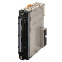
I/O Control Unit, I/O Interface Unit
Part Number
Configured Part Number is shown.
Specification Table of OMRON PLC
CJ1W-IC/II of OMRON PLC

PLC Appearance of CJ1W-IC101

PLC CJ1W-IC101 dimensional diagram Unit: mm
Note: Weight: 70g or less

PLC CJ1W-IC101 external interface

PLC Appearance of CJ1W-II101

PLC CJ1W-II101 dimensional diagram Unit: mm
Note: Weight: 130g or less (including end cover)

PLC CJ1W-II101 external interface
| Product Name | specification | Current consumption (A) | format | International Standards | |
|---|---|---|---|---|---|
| 5V system | 24V system | ||||
| CJ series I/O control unit | Use one unit to connect an expansion unit to the CPU unit. Connection cable: Expansion Connection Cable CS1W-CN□□3 Connection destination: CJ1W-II101 I/O Interface Unit Connect to the right of the CPU Unit. | 0.02 | - | Model CJ1W-IC101 | UC1, N, L, CE |
Note: Connecting the unit anywhere other than to the right of the CPU Unit may result in malfunction.
| Product Name | specification | Current consumption (A) | format | International Standards | |
|---|---|---|---|---|---|
| 5V system | 24V system | ||||
| CJ series I/O interface unit | One unit is required for the expansion device. Connection cable: Expansion connection cable type CS1W-CN□□3. Connect it to the right of the power supply unit. | 0.13 | - | Model CJ1W-II101 | UC1, N, L, CE |
Note: Connecting the power supply unit anywhere other than to the right may result in malfunction.
About overseas standards
- The symbols are as follows: UC1: cULus (Class I Div 2 hazardous location certified product), N: NK, L: Lloyd, CE: EC Directive.
- Please contact our support center for information on terms of use.
accessories
- CJ1W-IC101: None
- CJ1W-II101: End cover CJ1W-TER01 (required for the right end of the CPU unit), end plate PFP-M (2 pieces)
CJ1W-ID of OMRON PLC

PLC Appearance of CJ1W-ID201

PLC CJ1W-ID201 dimensional diagram Unit: mm

PLC Circuit diagram

External connection diagram/Terminal and device variable correspondence diagram
| name | DC input unit (terminal block, 8 points) |
|---|---|
| format | Model CJ1W-ID201 |
| Rated Input Voltage | DC12-24V |
| Allowable Input Voltage Range | DC10.2~26.4V |
| Input impedance | 2.4 kΩ |
| Input Current | 10mA TYP. (DC24V) |
| ON voltage/ON current | DC8.8V or more/3mA or more |
| OFF voltage/OFF current | DC3V or less/1mA or less |
| ON Response Time | 8.0ms or less (can be changed between 0 and 32ms depending on the setting) *1 |
| OFF Response Time | 8.0ms or less (can be changed between 0 and 32ms depending on the setting) *1 |
| Number of circuits | 8 independent contacts |
| Number of simultaneous ON points | 100% simultaneous ON |
| Insulation resistance | Between all external terminals and GR terminal: 20 MΩ or more (at 100 V DC) |
| Withstand voltage | Between all external terminals and GR terminal: 1000V AC for 1 minute, leakage current 10mA or less |
| Internal current consumption | DC5V: 80mA or less |
| mass | Under 110g |
| Circuit configuration | - The signal name of each terminal is the device variable name. The device variable name is the name when the device name is "Jxx". |
| External connection diagram/ terminal and device variable correspondence diagram *2 | ・The polarity of the input power supply can be either + or -. ・The signal name of each terminal is the device variable name. The device variable name is the name when the device name is "Jxx". |
Note: Although only 8 points can be used for external I/O, 16 points (1 CH) are occupied in the I/O allocation.
*1. When set to 1.0 ms, the ON response time will be 20 μs or less and the OFF response time will be 400 μs or less due to delays in internal elements.
*2. The connector pin numbers A0 to A8 and B0 to B8 shown in the external connection diagram and the diagram showing the correspondence between terminals and device variables are notations used in this data sheet. They are not shown onthe unit.
*The specifications shown are only a portion of the specifications.
| Part Number |
|---|
| CJ1W-IC101 |
| CJ1W-ID201 |
| CJ1W-II101 |
| Part Number | Standard Unit Price | Minimum order quantity | Volume Discount | Days to Ship | Number Of Inputs | Input Format | Rated Input Voltage (V) | Number of Outputs | Rated load voltage (V) | Connection Terminal | Current Consumption (A) | Name |
|---|---|---|---|---|---|---|---|---|---|---|---|---|
SGD 286.77 | 1 Piece(s) | 4 Day(s) or more | - | - | - | 1 | 5 | [Connector] Connector | 0.02 | I/O Control Unit | ||
SGD 193.97 | 1 Piece(s) | 4 Day(s) or more | 8 | [DC input] DC Input | 12–24 | - | - | [Terminal Block] Terminal Block | 0.08 | DC Input Unit | ||
SGD 379.39 | 1 Piece(s) | 4 Day(s) or more | 1 | - | - | 1 | 5 | [Connector] Connector | 0.13 | I/O Interface Unit |
Loading...
Basic Information
| Representative Standard | CE / UL / CUL / CSA |
|---|
Specification/Dimensions
-
Number Of Inputs
-
Input Format
- DC input
- DC input
-
Rated Input Voltage(V)
-
Number of Outputs
-
Rated load voltage(V)
-
Connection Terminal
- Terminal Block
- Connector
- Terminal Block
-
Current Consumption(A)
- 0.02
- 0.08
- 0.13
-
Name
- DC Input Unit
- I/O Control Unit
- I/O Interface Unit
Days to Ship
-
- All
- 4 Day(s) or Less
Specify Alterations
- The specifications and dimensions of some parts may not be fully covered. For exact details, refer to manufacturer catalogs .
Tech Support
- Factory Automation, Electronics, Tools, & MRO (Maintenance, Repair and Operations)
- Tel:(65) 6733 7211 / FAX:(65) 6733 0211
- 9:00am - 6:00pm (Monday - Friday)
- Technical Inquiry
Payment Method
- Credit Card
- PayPal
- Bank Transfer
Social Media
MISUMI Contact
Copyright © MISUMI Corporation All Rights Reserved.
How can we improve?
How can we improve?